
tpiprog
Synopsis and description
tpiprog [--direct-port=port] [--ppdev=device] [--calib-us] [calib-n=n] [--clock-t=T] [--hi-voltage] [--stat-progress] [--stat-flow] [--ignore-errors] [--interactive] [command ...]")
tpiprog utility communicates with microcontrollers over the TPI (Tiny Programming Interface) link and allows to read and write sections of chip's memory, including NVRAM. Full TPI protocol is implemented. Currently, a LPT dongle is supported as the interface. Included PCB supports 12-volt programming and allows accessing chips locked with RSTDISBL (reset disable) flag.
The only microcontrollers known to me to use the TPI is Atmel's ATtiny4, ATtiny5, ATtiny9 and ATtiny10 family. The hardware dongle supports both SMD and DIP chips as well as connector for in situ programming.
Downloading and compiling
Source code and manual pages: Requirements:- libarguments
- bash and make for easy compiling
- Edit
config.hfirst to customize the program - Run:
make
LPT dongle
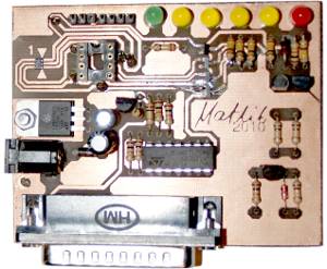
The LPT adapter for ATtiny4/5/9/10 allows both programming and testing the chip. All four outputs can be controlled individually. Additionally, the PB3 pin (!RESET) may be powered from a 12-volt source to allow the high voltage programming. It is based on the 74LS125 tri-state TTL buffer.
The board requires an external 6-12 V power supply for programming. The standard LPT outputs do not provide enough current to support flash write operations even though entering TPI mode and reading from memories is possible.
Both SOT23 and DIP8 connectors are available, as well as the 6-pin row connector for programming outside of the board. Mounting the SMD package is a bit tricky since you will need something to hold the chip in its place. I use a paper clip for that.
")
Board layout
")
Elements needed to build the dongle:
- DB25 male connector
- 2-pin and 4-pin row connectors
- DC connector
- DIP8 socket
- LED 5 mm: 1 × green, 4 × yellow, 1 × red
- Resistors 1/4 W: 6 × 220 Ω
- Resistors 1/8 W: 7 × 10 kΩ, 2 × 100 kΩ
- Electrolyte 16 V: 4.7 µF, 47 µF
- BAV20 or similar
- 1N5817, 1 A Shottky
- Zener 1/2 W: 6.2 V
- 2 × BC327-16, hFE 200+
- 2 × BC337-16, hFE 200+
- 4 × BSS123
- L78S05, TO92 may not deal with LED currents
- 74LS125 (DIP)
PCB
")
")
")
